Had a few gotchas during assembly: (Documenting for hopeful corrections) (and FYI, I actually watched the entire video assembly process first, but hadn't gotten the parts out yet so still missed a few details)
1. The video and pdf instructions go in different orders. Some assembly steps were clearer in the video and others in the PDF, so I was swapping back and forth. Difficult when they are in different orders and the steps vary a bit.
2. The 530mm 20x20 rails have only one that is threaded, but the initial steps didn't caution to look for the threaded one and leave it aside for the top rail. *Suggestion, note this in each use of the 20x20 rails*
3. There were no 4x12mm screws in the kit, but there were 4x14 without any other use, so I assume they were substituted.
4. Square bars had small holes in only one end that I didn't notice and that weren't called out in the manual. I got to step 52 in the printed manual and found out that I had inserted one of them wrong in step 24.
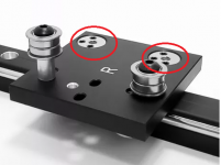
5. The metal plates that attach to the square bars are asymmetric (extra holes on one side), took some time to figure out that they didn't matter.
6. As SABO pointed out, the video assembly instructions show T nuts for the side rails and the PDF (and kit) show slide nuts.
7. The Print engine screen (vs the PI) does not fit on any of the rails and the instructions don't show it..
8. The camera doesn't seem to work "out of the box", will need to troubleshoot.
9. The X axis belt teeth rub on themselves just a little and I can't adjust anything further to separate them more.